General Sales Launch of DW07 Series High-current Busbar Connector
|
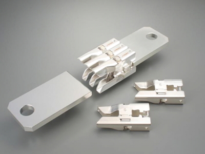
JAE has developed and started general sales of the DW07 Series connector, which was designed for busbar connection of devices requiring high-current power lines.
|
::Background
|
Utilizing busbars is very common in running large amounts of current in high-power infrastructure, as in cases of power conversion and energy storage systems.
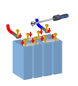
Traditionally, these systems require facilitating larger areas surrounding the busbars for an operator to physically bolt-down connection and to store large cable bundles. To increase space efficiency there is a growing demand for methods to reduce space required surrounding the connection areas. Along with space saving, there have been increased requirements to improve time spent on connecting busbars by manual bolt-down methods.
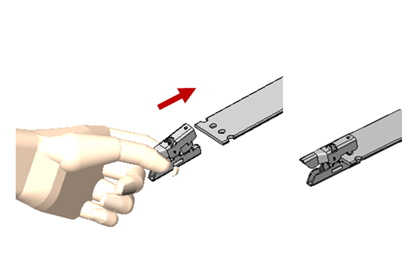
JAE has developed the DW07 Series busbar connector to meet these industry requirements. This innovative docking style busbar connector was designed to improve commonly sought after space saving and operation time issues. This connector solution allows for internalizing high-density wires within devices, and reduce operation space and hours spent fastening down bolts by making tool-less connection possible.
There are wide varieties of communication devices and industrial equipment that share similar configurations required of power conversion and energy storage systems. The DW07 Series is an ideal connector solution, catering to these wide range of applications, to simplify these high-current connection needs by improving operation time and space, supporting the demand for more efficiently run facilities.
|
 |
 |
| Fig. Conventional Screw Fastening Connection |
Fig. Busbar Connection Using DW07 |
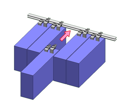 |
| Fig. Unit Connection Application Example |
:: DW07 Features
- Floating connection
The DW07 Series compensates for mis-alignment between the rigid busbars being connected.
- Flexible current amount
The required electrical current can be attained by the number of connectors used
- Attachment without using screws
Connector attaches easily with one hand by clipping onto mating holes in the busbar.
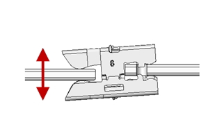 |
| Vertical Floating Tolerance: ± 2.5 mm |
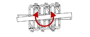 |
| Slant Floating Tolerance: ± 1.5 deg |
|
:: Applicable Markets
- Electric conversion and energy storage applications, and other applications using busbars
- Communication facilities and industrial equipment using busbars
|
:: Specifications
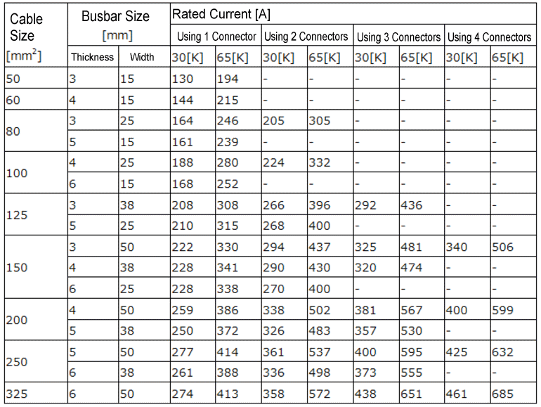
| Rated Current |
Please refer to the chart below. |
| Contact Resistance |
0.13 m ohms MAX. (initial) |
| 0.16 m ohms MAX. (posttest) |
| Insertion Force |
120N max. |
| Extraction Force |
50N max. |
| Durability |
100 times |
| Operating Temperature |
-25 Deg. C to +105 Deg. C
(including temperature rise from electrical current) |
| Applicable Busbar |
JIS H 3140 Silver Plating |
| |
Chart 1 Rated Current |
|
 |
| |
Note:
|
Rated current [A] = Current rate[A] temperature rise rate from 30[K] to 65[K] x safety ratio (80%)
Calculated values are based on utilizing the above mentioned cable size of 2m and busbar of 10cm.
Rated current depends on the size of the busbar and the number of the connectors used
|
|
Information and details given here are as of the date of publication.
Please note that the details may be changed.